-Installation Type 1
> Carefully constructed bed
> Backfill pipe zone to 300 mm over pipe crown with specified backfill material compacted to required relative compaction level.
Note: For non-pressure applications, requirement to compact 300 mm over pipe crown is not applied.
-Installation Type 2
>Backfill to a level of 60 % pipe diameter with specified backfill material compacted to required relative compaction level.
>Backfill from 60 % of diameter to 300 mm over pipe crown with a relative compaction necessary to achieve a minimum soil modulus of 1.4 MPa.
.png)
Note 1: Installation type 2 is not applicable to small diameters.
Note 2: Installation type 2 is not suitable for high traffic load conditions.
Alternative installations to accommodate a specific field condition include wider trenches, sheet piles, soil stabilization, geotextiles etc. Grandpipe installation instructions for buried pipe should be consulted for additional details.
.png)
Grandpipe GRP pipes can be installed in a number of different situations including aboveground, sub-aqueous, trenchless and sloped applications. These applications can require more initial planning and more care than standard buried pipe installation. Please contact Grandpipe for further information.
-Trenching
Trench must always be wide enough to permit placement and compaction of pipe zone backfill materials and provide proper pipe support. Depths of cover charts presented in this brochure are based on an assumed trench width 1.75 times the pipe's nominal diameter. Widths down to 1.5 times DN may be achievable, however burial limits will be affected. In extraordinary conditions, please consult to Grandpipe Expert Team.
.png)
-Bedding
Trench bed, of suitable material, should provide uniform and continuous support for pipe.
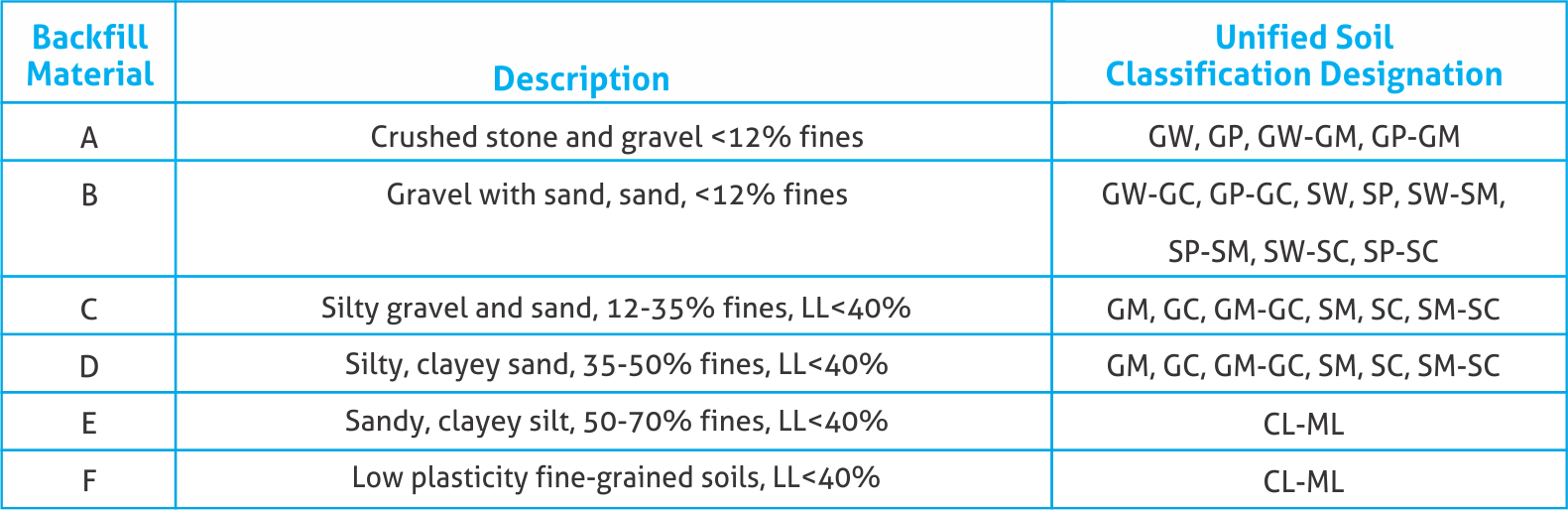
- Backfill Materials
To ensure a satisfactory pipe-soil system, correct backfill material must be used. Most coarse grained soils (as classified by Unified Soils Classification System) are acceptable bedding and pipe zone backfill material. Where the instructions permit the use native soil as backfill, care organic material. Following table identifies acceptable backfill soils:
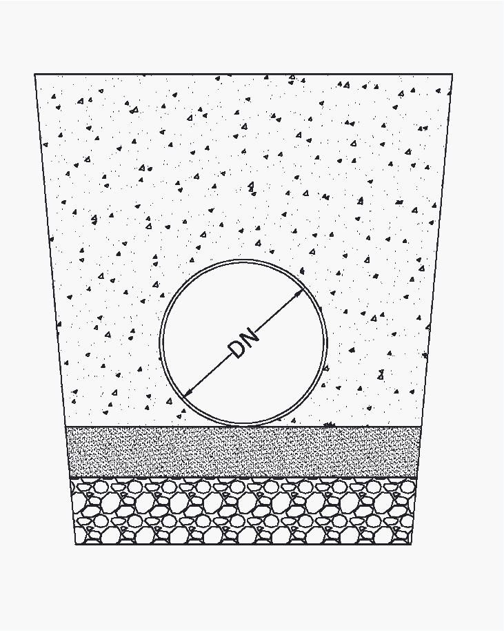
- Standard Trench Details
A typical trench detail for GRP pipe can be as following figure:
Dimension A is a minimum 0.75 DN / 2.
> Where rock, hard pan, soft, loose, unstable or highly expansive soils are encountered in trench bottom, it may be necessary to increase depth of bedding layer to achieve adequate longitudinal support.
> Dimension A must allow for adequate space to operate compaction equipment and ensure proper placement of backfill in haunch region. This may require a wide trench than minimum specified above (Particularly for smaller diameters ).

-Checking Installed Pipe
After installation of each pipe, maximum diametrical vertical deflection must be checked. For Grandpipe GRP pipes, this procedure is fast and easy.
- Installed Diametrical Deflection
Maximum allowable initial diametrical deflection (typically vertical) shall be as folloews:
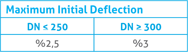
Maximum allowable long-term diametrical deflection shall be 5 % for diameters 300 mm and larger and 4 % for smaller diameters. These values will apply to all stiffness classes. Bulges, flat areas or other abrupt changes of pipe wall curvature are not permitted. Pipe installed outside of these limitations may not perform as intended.
- Traffic Load
All backfill to grade should be compacted when continuous traffic loads are present. Minimum cover restrictions may be reduced with special installations such as concrete encasement, concrete cover slabs, casing etc.
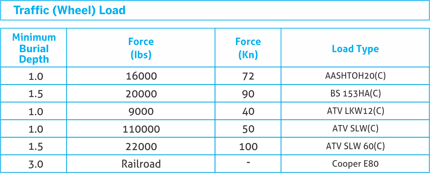
Based a minimum pipe zone backfill soil modulus 6,9 MPa.
-High Pressure
High pressure more than 16 bar may require deeper burial depth to prevent uplift and movement. Pipes - DN 300 and larger - should have a minimum burial depth of 1.2 meters, and 0.8 meters for smaller diameters.
-High Water Table
A minimum of 0.75 diameter of earth cover (minimum dry soil bulk density of 1900 kg/m3) is required to prevent an empty submerged pipe from floating. Alternatively, the installation may proceed by anchoring pipes. If anchoring is proposed, restraining straps must be a flat material – minimum 25 mm wide, placed at maximum 4 meter intervals – Please advise Grandpipe for details on anchoring and minimum cover depth with anchors.
- Joint Angular Deflection
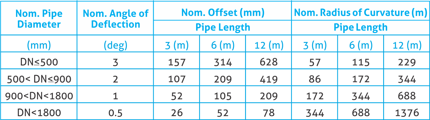
Coupling joints are extensively tested and qualified in accordance with EN 1119 ASTM D4161 and ISO 8639. Maximum angular deflection for each coupling joint – measured as change in adjacent pipe center lines – must not exceed the values given in table below.
Pipes must be joined in straight alignment but not all the way to home line and thereafter deflected angularly as required.
.png)
When GRP pipe system will be operated at pressures exceeding 16 bar, allowable angular joint deflection should be reduced to levels noted in following table.
.png)
.png)
-Surge and Water Hammer
Water hammer or pressure surge is sudden rise or fall in pressure causes by an abrupt change in fluid velocity with in pipe system. Usual cause of these flow changes is the rapid closing or opening of valves or sudden starting or stopping of pumps such as during a power failure. Most important factors which influence water hammer pressure in a pipe system are variation in fluid velocity, rate of change of the velocity (valve closing time), compressability of the fluid, stiffness of the pipe in hoop direction and physical lay-out of the pipe system.
Where similar conditions are considered for GRP, steel and ductile iron pipes, water hammer pressure assumed for GRP pipes is approximately 50 % less than the others. Grandpipe GRP pipes have surge pressure allowance of 40 % of nominal pressure.
An approximate relationship for maximum pressure variation at a given point in a straight pipeline with negligible friction loss can be calculated from the formula.